
COVID COASTER
TCNJ Engineering Senior Project 2020-2021
PROJECT UPDATES
What We’ve Done

SEPTEMBER UPDATES
So far in our project, Nick and Elyse have been working in the preliminary stages of the design work. This includes researching CDC guidelines, motors, railways, and drivetrain frameworks. The team met with the machine shop supervisor, Joe Zanetti, to discuss the prototype plans for the cart. Part of the preliminary work has also focused on the budgeting for the project and submitting a range to the mechanical engineering department. We hope to begin modeling some sample designs soon in Solidworks.
Yariel and Yamir are continuing ongoing research regarding potential restrictions and clearances that must be adhered to during the design of a rollercoaster. They have also began to discuss potential placements of supports for the roller coaster and feasible layouts on campus for the roller coaster. They are awaiting loading information from Nick and Elyse to find the maximum moment so that the structural analysis can begin. The team is attempting to get in contact with an individual or individual that possesses a strong expertise in the design of roller coasters that might be able to assist them on the project.
OCTOBER UPDATES
October 18, 2020 9:00 AM
This month for the project, Nick and Elyse developed list of criteria for their car design, and begun brainstorming ideas for their preliminary designs. Based on the criteria the team has chosen three designs and has begun developing models using SOLIDWORKS. The team hopes to finalize all aspects of their design and begin on a final design model to be created in SOLIDWORKS.


OCTOBER UPDATES
October 22, 2020 8:04PM
This month for the project Yariel and Yamir finalized the location of the coaster around campus with the campus architect. They also worked on different span lengths for the coaster as shown and presented them in their alternative designs presentation. Alternative Design 1 featured evenly spaced span lengths at 40 feet, Alternative Design II featured shorter spans 40 ft and under and Design III featured long spans ranging from 60-80 ft.
OCTOBER UPDATES 2
October 27, 2020 3:05 PM
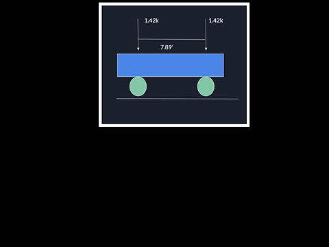
In the month of October, Yariel and Yamir received the cart dimensions as well as the cart load from the mechanical engineers. Using the loading case, the maximum moment and impact loading were calculated for all three alternative designs.

NOVEMBER UPDATES
November 29, 2020 8:54PM
Based on the topography map provided by the school architect, Yamir was able to determine the height of each support relative to the topography on the site. This was done by overlaying the topography map file of the site over the CAD drawing of the track layout.
NOVEMBER UPDATES 2
In the month of November, Yariel focused on designing the rail track. Yariel first began designing an 80 foot span but noticed that the size of steel necessary for allowable deflection was far too big and would run the cost of this project up greatly. For that reason, he decided to experiment with the 50 foot span detailed in alternative design II. He first started with HSS6.875x.500 and noticed that the HSS6.875x.500 failed where the loading was applied. Yariel then decided to increase the size of the railtrack where the loading is applied to HSS8.625x.625. He then made the bracing HSS4.5x.375 in order to reduce the weight of the steel. Of all the alternative designs, it was determined that alternative design II, a site layout with 50 foot spans would be the final design (RailTrack Pictured. This was determined due to the weight of steel required for Alternative Design III and the # of supports for Alternative Design I. Alternative Design II had around 87 supports, almost half of Alternative Design I and was only slightly heavier.

DECEMBER UPDATES
The full team finalized their designs and compiled a report to show all work. The cart was assembled with the appropriate wheel attachments in SOLIDWORKS and the track was modeled in AutoDesk. Members explained their work in two presentations for the Civil and Mechanical Engineering departments
JANUARY UPDATES
Elyse and Nick worked on developing the launching and braking systems for the coaster. Through decisions matrices, the team decided to use Electromagnetic motors to both propel and decelerate the vehicle during the ride. To correlate with the track, the coaster will be using vertical magnetic fins.
In addition, changes were made to the original car shape to give a more aerodynamic functionality and aesthetically pleasing look to the car. The team's purchase of Planet Coaster was approved as a cheaper and better software for simulating the rider experience.

FEBRUARY UPDATES
Mechanical update
February 26, 2021 8:08p.m
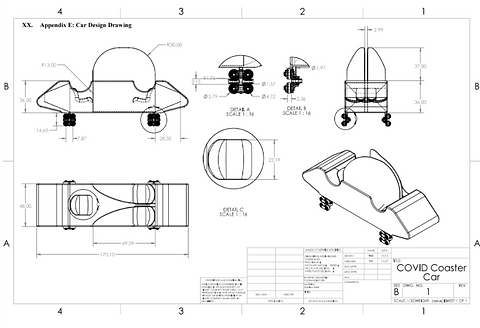
The mechanical engineers have updated their previous cart design and have finalized it. This design was selected because it is proven to be the most optimal and efficient design. It improves on the previous carts aerodynamics and aesthetic look.
CIVIL UPDATE
February 28, 2021 10:09p.m
The team has worked on finalizing the HSS steel rail track and proposed a track with W shapes. This has been updated and prepared per Dr. Al-Omaishi's request and is ready to be presented to him so that the final design can be chosen.

MARCH UPDATES
March 15, 2021. 10:51p.m
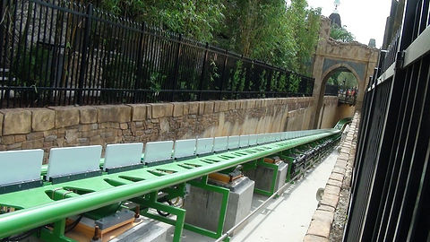
This month, the team focused on designing the platforms for the rollercoaster. This was done on Visual Analysis. These platforms will service as stops/stations for students to board and get off of the roller coaster at different points throughout campus.
_PNG.png)


CONNECTION DESIGN/SELECTION
March 27, 2021 11:15a.m
The team worked on selecting connections for the bream to girder and beam to column. We selected a w14x48 beam connected to a w10x45 girder using welds A, 3/16th weld on the bottom of the top flange and on the bottom of the bottom flange. Pictured are the steel angles used to connect the beam and girder. This features two 13/16th diameter holes on each angle which was welded onto the girder using welds A, 3/16th weld. The the Beam is attached to it using Welds B ¼ inch weld both on the bottom of the top flange and the bottom of the bottom flange. Pictured is also the angles used to connect the beam and column. This was welded using Welds B ¼ inch weld. The angles used 3 13/16 diameter holes and will use ¾ inch bolts.
APRIL UPDATES
April 20, 2021 1:03p.m
After having the original hinge connection reviewed, the team was told by it's advisor that it would be more beneficial to incorporate a seated connection design. This was done for the beam to girder, beam to column and girder to column connections.

APRIL UPDATES
April 21, 2021 2:10p.m
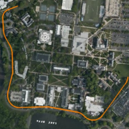
After receiving comments during the poster presentation regarding a lack of visuals that accurately represent the layout of the coaster, the team decided to finalize their site layout and demonstrate exactly where the coaster travels through campus on AutoCad.